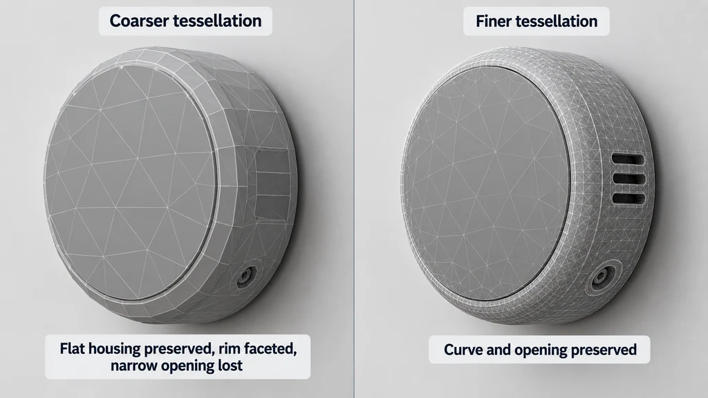
Start with a confirmed CAD revision and units. Tessellation approximates the supplied surfaces. It does not repair an incorrect design or determine which assembly revision the marketing team intended to show.
Select representative problem regions
Identify a broad curve, a small radius, a hole, and a surface junction that appear in the intended views. Keep these regions in the first comparison rather than meshing the entire catalog with untested settings.
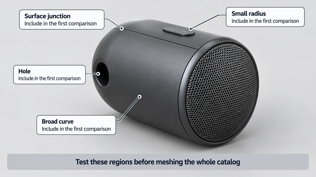
Record the closest approved camera. A coarse result may be acceptable for an overview and unacceptable for a macro view. Decide the usage before treating either result as correct.
Check the imported CAD for missing surfaces or invalid geometry. Do not compensate for a failed import by adjusting the meshing tolerance.
Understand what the mesh is approximating
A STEP model can describe curved CAD surfaces. A real-time triangle mesh approximates those surfaces with planar pieces. Coarser tessellation can flatten the silhouette of a small radius even when smooth shading makes the broad face look continuous.
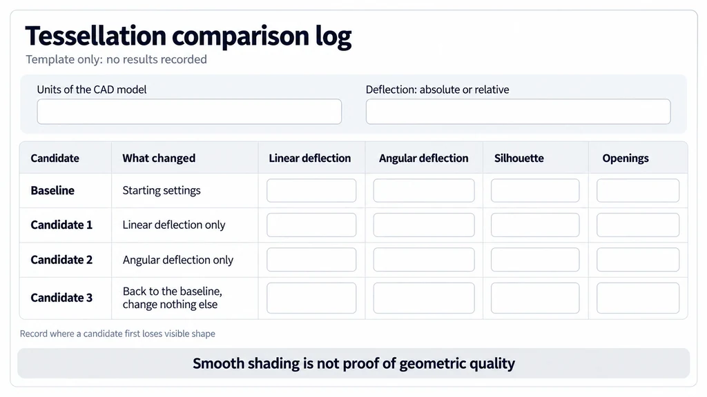
A deflection parameter controls an approximation criterion according to the mesher's definition. An angular parameter can add control over changing surface direction. Absolute and relative settings are not interchangeable, and a numeric tolerance is meaningless without its units and interpretation.
Start with one shell containing a broad curve, a tight fillet, and a narrow opening. Create a few candidates from the same CAD revision and compare those regions at the approved camera distance. Choose the least costly candidate that preserves the required evidence, then apply and review the settings on the wider assembly. This makes the tolerance a documented production choice instead of an unexplained default.
Compare controlled tessellation candidates
Use the mesher's documented parameters and record their units and interpretation. Open CASCADE's meshing guide explains deflection-related controls. Another tool may expose different labels or relative settings, so do not transfer a number without checking its meaning.
Change one parameter at a time. Compare silhouettes and openings at a fixed view, then move the review light across curved surfaces. Record where a candidate first loses visible shape.
Avoid treating smooth shading as proof of geometric quality. It can soften the appearance of a coarse surface while the outline remains faceted.
Inspect junctions and small features
Check adjacent surfaces for cracks, shading discontinuities, and unexpected boundaries. Examine the inside of openings and thin parts. A model that looks intact from the front may fail from below.
Confirm that small features remain relevant to the delivery. If a manufacturing detail is intentionally omitted, record that as a simplification decision. Do not label an accidental loss as optimization after discovering it.
For a rounded product shell, compare the outer silhouette and a nearby screw recess independently. They may require different care even when they share the same material.
Keep meshing separate from later reduction
Retain a reviewed tessellation before applying mesh simplification or compression. Tools such as glTF Transform simplify operate on the resulting mesh and introduce a different decision about geometric loss.
Compare each stage with its own input. If the final rim is distorted, you need to know whether tessellation or later reduction caused it.
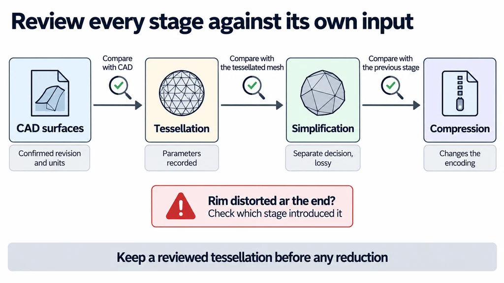
Deliver the selected parameters, source revision, and comparison views with the mesh. Report actual file size and triangle counts only for the produced files. Avoid presenting one successful tolerance as a universal setting for every CAD product. A useful tessellation recipe is reproducible and tied to the visible features it preserves.