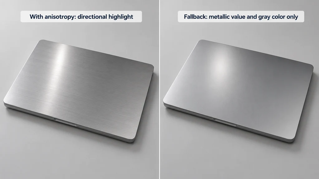
Use the glTF anisotropy extension only when the chosen delivery path supports it. An export containing the extension is not proof that every viewer will render the same appearance.
Establish the finish direction
Confirm the direction from the product reference. Separate linear brushing from circular machining or a finish whose direction changes across parts. Keep the intended direction recorded per component.
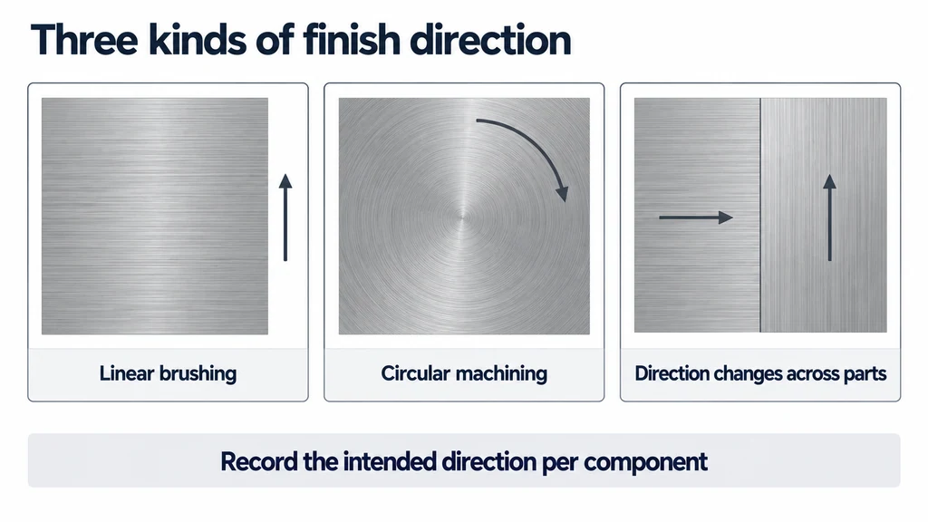
Use a simple test surface before applying the material to the full assembly. Choose lighting that makes the directional response visible. Avoid starting with a complex environment in which several reflections can obscure the result.
A reference photograph shows the finish under a particular light. Obtain additional evidence if it is unclear whether the observed streak is surface structure or a reflected object.
Author a controlled direction test
The KHR_materials_anisotropy specification defines the extension's controls and texture interpretation. Follow those definitions rather than assuming an authoring tool's slider maps directly to the exported value.
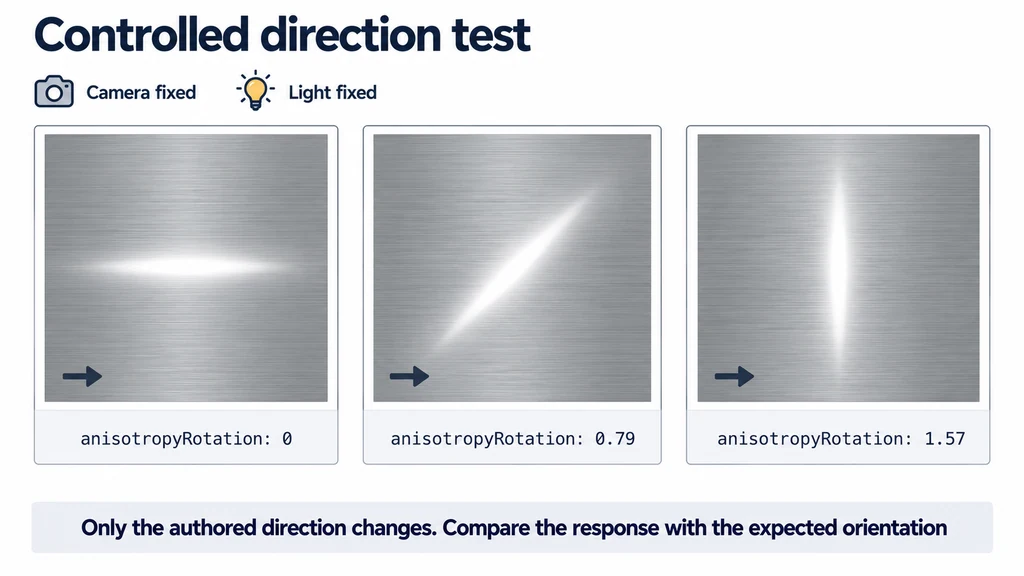
Create an obvious orientation marker on the test geometry for review, separate from the final product material. Change the authored direction while keeping the camera and light fixed. The comparison should show whether the exported material responds in the expected orientation.
Inspect tangent handling and UV layout when the result rotates unexpectedly across adjacent regions. Do not compensate by changing the environment for each component. That conceals a directional inconsistency.
Inspect the exported anisotropy controls
KHR_materials_anisotropy defines anisotropyStrength, anisotropyRotation, and an optional anisotropyTexture. Rotation is in radians in the relevant tangent frame. The texture's red and green channels encode the local direction; blue contributes strength. Treat it as material data rather than an sRGB photograph.
For example, the following material-extension fragment describes a constant directional response without a texture:
{
  "KHR_materials_anisotropy": {
    "anisotropyStrength": 0.6,
    "anisotropyRotation": 0.0
  }
}
The values are illustrative. The material must sit inside a correctly declared, complete glTF asset and be supported by the target renderer.
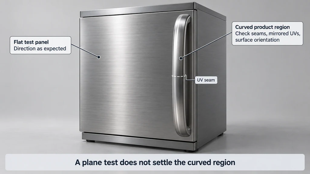
Inspect the tangent frame across UV seams and mirrored regions. Explicit exported tangents and the extension's permitted fallback derivation need checking in the selected runtime; absence of an authored tangent attribute does not by itself prove that every asset will fail. Review a known direction marker on a plane, then on the curved product. Linear brushing and radial machining require different direction fields even when their average color is similar.
Verify the receiving renderer
Check the specific loader and renderer version. The Three.js GLTFLoader documentation identifies supported extensions for that implementation, but a deployed application may use a different version or a modified material path.
Review the exported material on a flat panel and on the actual curved product region. A test that works on a plane does not settle the result across seams, mirrored UVs, or changing surface orientation.
Keep the light and exposure conditions documented. Compare material character rather than demanding pixel equality between different rendering systems.
Approve the fallback explicitly
Decide what the product should look like when directional response is unavailable. A restrained non-anisotropic material may preserve the broad finish category, but it can lose an important selling detail.
If the finish cannot be represented acceptably without anisotropy, treat the unsupported destination as a compatibility limitation. Provide an approved alternative representation rather than silently displaying a materially different product.
Deliver the extension list, the tested renderer version, and the reference views with the asset. Name the parts whose direction was reviewed. Acceptance should cover both the supported rendering path and the fallback, not only the most attractive preview.