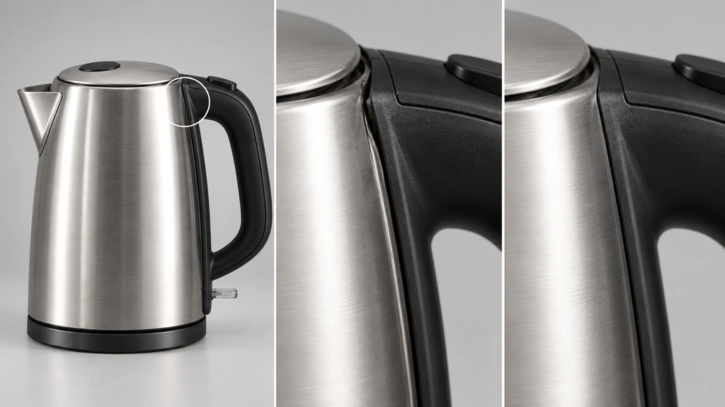
A model that works in a wide product image may need more attention before a close camera move. Small panel intersections and uniform bevels become easier to notice when they fill the frame. This 3D Vision Art modeling note starts with the camera so effort goes into details the final image can actually reveal.
Fix the comparison view
Save the closest intended framing of each important region. Use that same view when revising the geometry, and compare at the intended output size. A wider camera position can conceal a defect without correcting it.
Record the intended use. An exterior still and a rotating macro animation may require different levels of construction, even when they show the same product.
Match the edge to the reference
Look for panel thickness, seam width and edge radius in reference photographs or drawings. Molded transitions and sharp sheet edges should not automatically receive the same bevel treatment.
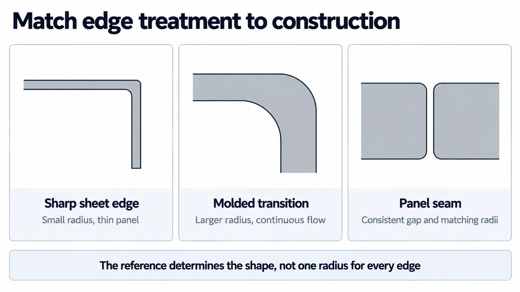
Use a broad highlight to inspect the edge. Check corners for pinching and intersections. Adjust the review light before enlarging a bevel simply to make the reflection easier to see, because that change can alter the apparent construction.
Decide what needs depth
Use geometry when a detail changes the outline, creates a visible opening, shows thickness or moves independently. Evaluate shallow surface variation through the material when it does not need those properties in the approved view.
A painted dark slot may suggest a vent at a distance but fail when the camera reveals its side. Fine grain, on the other hand, may be represented adequately by a texture rather than thousands of modeled grooves. Test both decisions under more than one light direction.
Review a seam as a construction detail
Choose a panel junction from the product reference and compare its width, depth, and termination. A seam that remains visible only because it is painted black can fail when the camera moves sideways. Conversely, a shallow mark that never changes the outline may be represented adequately by a normal map.
| Evidence in the approved view | Representation to evaluate |
|---|---|
| Visible opening, side wall, or changing silhouette | Modeled depth and thickness. |
| Small surface direction changes without visible depth | Normal or bump detail. |
| Independent movement or assembly clearance | Separate geometry with a controlled transform. |
| Printed marking | A texture with enough UV coverage and source detail. |
Check the smallest bevel under a broad highlight and in neutral shading. Its width should follow reference evidence rather than a universal radius. Keep the final camera, image dimensions, and crop in the comparison. Enlarging the output or allowing a closer orbit changes the detail requirement and may justify another delivery version.
Review the whole object again
Inspect transitions between flat and curved regions, the ends of panel gaps and repeated components. Use neutral shading to distinguish geometry problems from material problems.
Finish by checking the close-up, another angle and a wider view. The added detail should improve the near view while preserving the overall proportions. Keep the construction editable so a revised radius or opening does not require rebuilding the asset.